
TEC Controllers
A TEC controller, also called a Peltier controller, holds one thing at one temperature. It reads a temperature sensor, then pushes current through a thermoelectric cooler — a Peltier module. Send the current the other way and the same module heats instead of cools, so one part covers both directions. Use a controller when a laser diode, a detector or a sample has to stay at a set temperature while the room does not. If you only need to set a laser diode’s drive current, buy a laser driver instead. If you need the Peltier module itself, see TEC Modules.
ATI builds 87 TEC controllers, from 2.5 A to 15 A, starting at $52. The output stage uses a patented single-PWM design that needs fewer parts and less board space than the usual two-PWM approach. Most families have a matching evaluation board, so you can test the controller with your real TEC module, sensor and heatsink before you release a PCB. Selected models tune their own PID loop in about a minute, so you do not have to.
Filter and compare TEC controllers
Four filters narrow 87 models. Start with Max Current, because the TEC module decides it. Then Input Voltage to match the rail you already have, Package for DIP or SMT, and Stability Class — Standard, Mid and High Precision correspond to set-point accuracy of ≤5 mV, ≤2 mV and ≤0.5 mV or better. Every product page lists TEC output voltage, price, stock and the datasheet.
Showing 1–12 of 87 resultsSorted by price: low to high
| Image | SKU | Max. Current | Input Voltage | Max. Output Voltage | Temp Stability | Features | Datasheet | Price | Stock | Action |
|---|---|---|---|---|---|---|---|---|---|---|
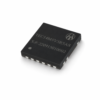 |
TEC14M5V3R5AS | 3.5A | 2.7V ~ 5.5V | ±VVPS | 0.001°C | Bipolar | $52.00 | 5 | ||
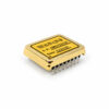 |
TECA1-3V-1.3V-D | 2.5A | 3.3V | ±1.3V | ≤5mV | Bipolar | $79.00 | 4 | ||
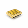 |
TECA1-5V-2.5V-D-OP | 2.5A | 5V | ±2.5V | ≤5mV | Bipolar | $79.00 | 58 | ||
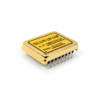 |
TECA1-5V-2.5V-S-OP | 2.5A | 5V | ±2.5V | ≤5mV | Bipolar | $79.00 | Made to Order | ||
 |
TECA1-5V-3V-D | 2.5A | 5V | ±3V | ≤5mV | Bipolar | $79.00 | 7 | ||
 |
TECA1-5V-5V-D | 2.5A | 5V | ±5V | ≤5mV | Bipolar | $79.00 | 28 | ||
 |
TECA1-5V-4V-D | 2.5A | 5V | ±4V | ≤5mV | Bipolar | $79.00 | 5 | ||
 |
TECA1-5V-3.5V-D | 2.5A | 5V | ±3.5V | ≤5mV | Bipolar | $79.00 | Made to Order | ||
 |
TECA1-5V-2.5V-D | 2.5A | 5V | ±2.5V | ≤5mV | Bipolar | $79.00 | 106 | ||
 |
TECA1-5V-2V-D | 2.5A | 5V | ±2V | ≤5mV | Bipolar | $79.00 | 36 | ||
 |
TECA1-3V-3V-D | 2.5A | 3.3V | ±3V | ≤5mV | Bipolar | $79.00 | 59 | ||
 |
TECA1-3V-2.5V-D | 2.5A | 3.3V | ±2.5V | ≤5mV | Bipolar | $79.00 | 17 |
Our Delivery Promise
Fast, flexible fulfillment from San Jose, California, USA — shipped worldwide.
- Fast in-stock shipping — In-stock orders ship within 1–2 business days after confirmation and quality check.
- Made-to-order models — Some models are produced to order. Contact sales@analogti.com for the current lead time.
- Worldwide shipping — Shipped from San Jose to customers worldwide.
- Flexible carrier options — UPS, FedEx, DHL, USPS, freight forwarders, or your preferred logistics partners.
- Clear shipment visibility — Tracking provided after dispatch to support your receiving and production planning.
Which family do I need?
Seven families. Two questions separate them: how much current your TEC module needs, and what supply rail you already have. Everything else — package, precision grade, sensor type — is chosen inside the family. Find your row, then filter above by current and input voltage.
| Family | TEC current | Runs from | TEC output | Precision | Sensor & package | Eval board | Choose this if… |
|---|---|---|---|---|---|---|---|
| TECA1 25 models | 2.5 A | 3.3 V · 5 V | ±1.3 V to ±5 V | ≤5 mV standard≤0.5 mV high precision | ThermistorDIP · some SMT | TECEV104 | This is where most designs start. A small module that sits on your board, cools and heats, and needs one low-voltage rail. The output voltage is fixed per part number, so pick the one that matches your TEC module instead of over-specifying. You add five compensation parts to match your thermal load. |
| TECA1LD 23 models | 2.5 A | 3.3 V · 5 V | ±1.3 V to ±5 V | ≤5 mV standard≤0.5 mV high precision | ThermistorDIP · some SMT | TECEV104 | Same as TECA1, but the loop is already tuned. The compensation network is inside the module. No external parts to calculate, no board space for them. Take this one if the thermal load is small and ordinary, and you would rather not spend a week tuning. |
| TEC14M 1 model | 3.5 A | 2.7 – 5.5 V | ±V of the input rail | 0.001 °C class | ThermistorSMT, 14 × 14 × 2.2 mm | TEC14MEV1.0ships with the controller | Space is the problem. The smallest controller ATI makes, and the cheapest. It also runs down to 2.7 V, so it works on a battery rail where the other families do not. Output voltage follows whatever you feed it. |
| TEC5V4A / TEC5V6A 6 models | 4 A · 6 A | 5 V | ±4.8 V · ±4.7 V | ≤5 mV standard≤2 mV precision≤0.5 mV high precision | ThermistorDIP | TECEV104 | You have a 5 V rail and need more than 2.5 A. Three precision grades of the same part, at the same price, so choose on the accuracy you need rather than on budget. The usual choice for a laser module that has outgrown TECA1. |
| TEC9V7A 6 models | 7 A | 5.5 – 9 V | ±8.5 V | <±0.001 °C | Thermistor · RTD · IC sensorDIP · SMT | TEC24V15AEV2.2 | A larger TEC on a 9 V rail. The high-power families are a step up in every direction: more current, a choice of sensor type, and an Auto-PID version that tunes its own loop. Bigger body, higher price. |
| TEC12V6A / TEC12V9A 10 models | 6 A · 9 A | 5.5 – 12 V | ±11.5 V | <±0.001 °C | Thermistor · RTD · IC sensorDIP · SMT | TEC24V15AEV2.2 | A 12 V rail is what you have. Two current ratings on the same platform. Take the 9 A version if the TEC is close to 6 A, because a controller running at its limit runs hot. |
| TEC18V6A / 10A / 15A 16 models | 6 A · 10 A · 15 A | 5.5 – 18 V | ±17.5 V | <±0.001 °C | Thermistor · RTD · IC sensorDIP · SMT | TEC24V15AEV2.2 | The largest thermal loads. Multi-stage TECs, thermal plates, test fixtures and cooled chambers. 15 A at ±17.5 V is the top of the range. Auto-PID versions are worth the extra here, because loads this size are the slowest to tune by hand. |
Reading the part number:
- -D: For example, TECA1-3V-1.3V-D. The controller comes in a DIP package.
- -S: For example, TEC14M5V3R5AS. The controller comes in an SMT package.
- D, DA, DAH: The precision grade, in that order. DAH parts hold the set point to within 0.5 mV, DA to 2 mV, plain D to 5 mV.
- U: For example, TECA1-5V-2.5V-DU. The controller supports cooling only and cannot provide heating.
- LD: For example, TECA1LD-5V-4V-D. The controller comes with an internal compensation network.
- -OP: For example, TECA1-5V-2.5V-D-OP. The controller does not have the two pull-to-midpoint resistors on the TEMPSP pin, unlike controllers that include these two resistors. See the datasheet for details. The controller also does not have the 500 kΩ resistor between the TEMPSP pin and a 1.5 V voltage source, unlike other controllers that include this resistor.
- APID: For example, TEC18V15ADAPID. The controller measures the thermal load and sets its own PID compensation, in about 60 seconds. Available on the 9 V, 12 V and 18 V families.
- SNCO: For example, TEC9V7ASNCOD. Pin 1 carries a 600 kHz synchronisation output instead of the standard 85 Hz thermistor reference signal. Send it to another switch-mode controller or power supply so the two switch together, which removes the beat interference between them. Order the standard part unless you have that interference problem.
- Custom: A different output voltage, current or package can be built for OEM quantities. Tell us what you need.
Three things decide whether it works
A TEC controller is easy to buy and easy to disappoint. These are the three that catch people out.
- The TEC module sets the current, not the controller. Look up the maximum current and maximum voltage of your Peltier module first, then pick a controller that clears both with margin. A controller running at its rated limit gets hot and has nothing left for the pull-down at start-up. If the TEC needs 5 A, buy the 6 A part.
- Stability is a property of the whole system. The controller is specified in millivolts at the set-point pin — that part is guaranteed. Turning that into 0.001 °C at your device also needs the sensor mounted on the object itself, compensation matched to the load, insulation, and an ambient that is not swinging. Move the sensor 10 mm away and the number changes.
- The heat has to go somewhere. A TEC pumps heat out of your device and adds its own electrical power on top. The heatsink on the hot side has to remove both. This is the most common reason a system will not reach its target temperature, and no controller can fix it.
- Compensation is not optional on the standard families. Five parts — Rd, Cd, Ri, Ci, Rf — match the loop to your thermal load. Get them wrong and the temperature oscillates or crawls. Use an evaluation board to find them, take the LD version to skip the job, or take an APID version to have it done automatically.
Not sure which part fits your TEC module? Ask engineering — send the TEC module part number, the supply rail you have, and the temperature you need to hold.
Features & Advantages of ATI TEC Controllers
Why choose ATI TEC controllers? Because they help engineers reach stable, efficient thermoelectric temperature control with less design risk — through a patented power-stage topology, tunable PID compensation, full EMI shielding, evaluation board support, and long-term product continuity.
- Patented Single-PWM Topology — ATI’s single-PWM power-stage topology, U.S. Patent 6,486,643 B2, delivers bidirectional TEC current with one PWM engine where conventional designs use two. That helps reduce switching losses, component count, PCB area, and system heat.
- Auto-PID Self-Tuning Compensation — Selected ATI TEC controllers evaluate the thermal load and configure PID compensation automatically, in approximately 60 seconds. This reduces manual tuning time. Recommended models include TEC18V15ADAPID for DIP integration and TEC18V15ASAPID for SMT applications.
- Full Bidirectional EMI Shielding — Every ATI TEC controller module comes in a full metal enclosure. On most models the metal closes on all six sides, with only the pins exposed; a few models use a PCB base. The enclosure helps reduce capacitive, inductive, radiated, and conducted EMI coupling. This is especially valuable when the TEC controller is placed near laser drivers, photodetectors, precision ADCs, optical sensors, and other noise-sensitive analog circuits.
- User-Tunable Compensation Network — ATI TEC controllers expose five compensation components — Rd, Cd, Ri, Ci, and Rf. Engineers can tune the PID loop to the actual thermal load, instead of relying on one-size-fits-all compensation. LD-suffix variants, such as TECA1LD-xV-xV-D and TECA1LD-xV-xV-DAH, include an internal compensation network for plug-and-play use.
- Evaluation Boards for Fast Validation — ATI evaluation boards let engineers test the controller with the real TEC module, sensor, heatsink, and thermal load before final PCB release. Recommended platforms are TECEV104 for the TEC5V4A, TEC5V6A, and TECA1 families; TEC24V15AEV2.2 for the TEC9V7A, TEC12V and TEC18V series; and TEC14MEV1.0 for micro TEC controllers.
- Full Product Span from Micro to High Power — ATI offers TEC controllers from compact micro modules to high-current controllers. The range covers different input voltages, output currents, package styles, precision grades, and integration needs. Representative models include TEC14M5V3R5AS, TEC5V4A, TEC5V6A, the TECA1 series, and TEC18V15A.
- Long-Term Product Continuity — No ATI TEC controller has been discontinued. Every model introduced remains in active production. ATI also provides pin-compatible upgrade paths where available, and direct engineering support. This helps OEM customers reduce redesign risk and avoid unexpected end-of-life issues.
Learn more about how ATI TEC controllers work. For full specifications, see the individual product pages above.
Typical Applications of ATI TEC Controllers
Where are ATI TEC controllers (Peltier controllers) used? Across photonics, imaging, test & measurement, medical diagnostics, and OEM thermal-control systems — wherever stable bidirectional heating and cooling, low-noise operation, and repeatable temperature regulation are required.
- Laser diode cooling & wavelength stabilization — DFB lasers, VCSELs, pump lasers, and QCL modules need stable package temperature. Without it, the wavelength drifts, output power varies, and the spectrum degrades. Typical starting models include TEC5V6A-DAH for compact laser modules and TEC18V15A for higher-power photonics packages.
- Photodetectors, APDs & optical receivers — Detector gain, dark current, and noise can drift with temperature. ATI TEC5V4A-DA helps stabilize photodetectors, APDs, SPAD modules, fiber-optic receivers, LiDAR receivers, and low-noise optical front ends.
- IR sensors & cooled imaging sensors — IR sensors, CCD cameras, CMOS sensors, and compact thermal-imaging modules use TEC cooling to reduce dark current, pixel noise, and temperature-related image drift. Typical starting models include TEC14M5V3R5AS and TEC5V4A-D.
- LiDAR & optical communication modules — Laser transmitters and optical transceivers need stable TEC control to hold their wavelength as the ambient temperature changes. TEC5V4A-DA and TEC5V6A-DA are practical starting choices for compact automotive LiDAR, datacom transceivers, and DWDM optical modules.
- Optical test & measurement instruments — Optical spectrum analyzers, wavelength meters, interferometers, OCXOs, FBG interrogators, and precision timing modules require stable internal laser, detector, or oscillator temperatures. TECA1-xV-xV-DAH and TEC5V6A-DAH are suitable high-stability options, when paired with proper insulation, sensor placement, and compensation tuning.
- Semiconductor, sensor & battery test fixtures — Device-under-test fixtures, thermal plates, and battery-cell test setups need controlled heating and cooling during characterization or production screening. TEC18V15A is a common high-current starting model for these fixture-level applications.
- Medical diagnostics & life-science instruments — PCR blocks, ELISA incubators, sample holders, DNA sequencers, and diagnostic thermal stages depend on repeatable thermal profiles. TEC18V15A supports medium-size thermal loads that require controlled bidirectional temperature regulation.
- Custom OEM thermal platforms — For application-specific thermal loads, sensors, and mechanical designs, ATI evaluation boards — TECEV104, TEC24V15AEV2.2, and TEC14MEV1.0 — help engineers validate the controller, TEC module, and compensation network with the actual thermal load, before committing to a final PCB.
How to choose the right TEC controller
A practical workflow for matching a controller to a TEC module and application.
1. Define the temperature requirement
Identify the target temperature, stability, ambient range, and whether the load needs cooling, heating, or both.
2. Match TEC current and voltage
Select a controller with enough output current and voltage for the TEC module, with safe operating margin.
3. Choose the input-voltage family
Match the controller to the available system supply. ATI TEC controller families cover input voltages from 2.7 V to 18 V, spanning compact low-voltage to high-power applications.
4. Select the stability grade
Use D for general control, DA for higher precision, and DAH for ultra-stable laser or optical applications.
5. Check sensor placement
Mount the sensor directly on the controlled object to reduce delay, gradients, and temperature error.
6. Validate the full thermal system
Confirm the TEC, heatsink, sensor, controller, and compensation values work together under real operating conditions.
TEC controller FAQ
Common questions about selecting and using ATI TEC controllers.
What is the difference between a TEC controller and a TEC driver?
A TEC controller is a closed-loop system. It reads temperature feedback and adjusts TEC current automatically to hold a setpoint. A TEC driver is open-loop — it only delivers a commanded current, and needs external logic or firmware to close the temperature loop. Use a controller when temperature accuracy matters. Use a driver when an external MCU handles the regulation.
Is a Peltier controller the same as a TEC controller?
Yes. Both names describe the same device. It drives a thermoelectric cooler — also called a Peltier module — and holds it at a set temperature. TEC controller is the term used in most datasheets; Peltier controller is more common in general use. Every controller on this page works with any standard Peltier module, in both cooling and heating directions.
Can ATI TEC controllers both heat and cool?
Yes. ATI TEC controllers are bidirectional. They reverse the TEC current direction automatically to heat or cool, as needed to reach the temperature setpoint. No external polarity-switching circuit is required.
What temperature stability can ATI TEC controllers achieve?
Stability as fine as ±0.001 °C is achievable with DAH-grade controllers, such as the TEC5V6A-DAH. This requires the specified conditions: load-matched compensation, a precision thermistor, good thermal isolation, and stable ambient temperature.
What is the difference between D, DA, and DAH precision grades?
D grade provides ≤5 mV setpoint accuracy, DA grade provides ≤2 mV, and DAH grade provides ≤0.5 mV. Higher grades use tighter-tolerance internal components and lower-noise voltage references. Choose the grade based on the required temperature stability. DAH is recommended for wavelength-critical laser, optical, and precision instrumentation applications.
What input-voltage and TEC-current ranges are available?
ATI TEC controller families cover input voltages from 2.7 V to 18 V, depending on the model family. The micro TEC series operates at 2.7–5.5 V. The TEC5V series operates at 4.5–5.5 V. The TEC18V15A series operates at 5.5–18 V, with up to 15 A TEC current and ±17.5 V output. For higher-voltage or higher-current applications, contact ATI engineering.
What temperature sensors are supported?
ATI TEC controllers support NTC thermistors, platinum RTDs, and semiconductor temperature ICs, depending on the model. NTC thermistors are commonly used for the highest resolution near 25 °C. Platinum RTDs are preferred for the best long-term stability.
When should I use Auto-PID instead of manual tuning?
Use Auto-PID controllers, such as the TEC18V15ADAPID or TEC18V15ASAPID, when the thermal load varies between units, when the operating temperature range is wide, when tuning time is limited, or when field deployment requires fast setup. Use manual tuning with an evaluation board for fixed-load production systems, where the lowest possible noise and repeatable final compensation values are required.
How do I choose compensation values such as Rd, Cd, Ri, Ci, and Rf?
Measure the thermal load’s thermal time constant (τth) with a step-response test. Then set the loop crossover frequency to approximately fc = 1 / (5–10 × τth). Use the ATI evaluation board that matches your controller family to adjust Rd, Cd, Ri, Ci, and Rf while monitoring the temperature response. Refer to each product’s datasheet for the correct evaluation board part number. ATI datasheets provide starting-point values for common load types.
How does ATI reduce EMI in TEC controller designs?
Every ATI TEC controller module uses a full metal enclosure, closed on all six sides on most models, with only the pins exposed. A few models use a PCB base. The enclosure blocks capacitive, inductive, radiated, and conducted coupling paths. The shielding works in both directions. It helps protect the controller from external noise, and it helps reduce switching-noise coupling into nearby sensitive circuits, such as laser drivers, photodetectors, precision ADCs, and low-noise analog front ends.
How do I prevent condensation when cooling below the dew point?
When the controlled surface is cooled below the ambient dew point, moisture can condense. That causes corrosion, electrical leakage, shorts, or optical contamination. Seal the cold zone in a hermetic or dry-gas-purged enclosure, add desiccant if the enclosure is not perfectly sealed, monitor humidity, and set a minimum temperature limit in the control logic to prevent cooling below the local dew point.
Are ATI TEC controllers RoHS and REACH compliant?
Yes. All ATI TEC controllers are 100 % lead-free, RoHS-compliant, and REACH-compliant, and the certificates are on file: RoHS certificate and REACH certificate of compliance.