
TEC Controllers & Laser Drivers
A laser diode needs two things held steady: the current through it, and its temperature. Current sets the optical power, and a short overshoot destroys the diode. Temperature sets the wavelength, and it moves as soon as the room does. ATI builds a module for each loop — laser drivers for the current, TEC controllers for the temperature — plus the boards and dummy loads you use to prove the circuit before a real diode is at risk.
These are OEM modules for building into equipment, not benchtop instruments. The laser drivers cover linear, switching and pulse output stages in one catalog, the TEC controllers use a patented single-PWM output stage that needs fewer parts than the usual two-PWM approach, and both come in a metal enclosure because they usually sit next to the detector. Everything ships from San Jose, California.
Three groups, two loops
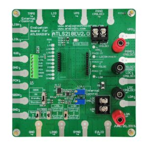
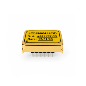
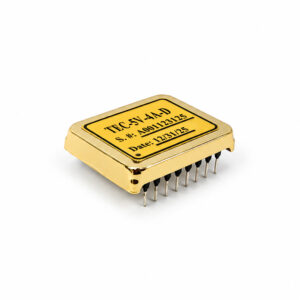
Laser Drivers set the current through the diode and limit it. TEC Controllers read a sensor and drive a Peltier module in both directions, so the same part heats and cools. Evaluation Boards — with dummy laser loads, a noise filter and a temperature plate — let you test either one against your real load first. Most laser modules need a part from each of the first two. The table below shows what each group contributes.
Our Delivery Promise
Fast, flexible fulfillment from San Jose, California, USA — shipped worldwide.
- Fast in-stock shipping — In-stock orders ship within 1–2 business days after confirmation and quality check.
- Made-to-order models — Some models are produced to order. Contact sales@analogti.com for the current lead time.
- Worldwide shipping — Shipped from San Jose to customers worldwide.
- Flexible carrier options — UPS, FedEx, DHL, USPS, freight forwarders, or your preferred logistics partners.
- Clear shipment visibility — Tracking provided after dispatch to support your receiving and production planning.
Which group do I need?
Three groups, one question each: are you setting a current, holding a temperature, or testing before the PCB is released? Everything else — current rating, package, precision grade — is chosen inside the group.
| Group | What it controls | Range | Runs from | Choose this if… |
|---|---|---|---|---|
| Laser Drivers 80 models · from $79 | Diode current | 50 mA – 45 A | 3 – 40 VDC100 – 240 VAC on chassis units | The optical power has to stay put. A constant-current source with the current limit, soft start and protection already built in. Linear models are the quietest, switching models reach the high currents, pulse models fire short bursts. |
| TEC Controllers 87 models · from $52 | Object temperature | 2.5 – 15 A TEC current | 2.7 – 18 V | The wavelength, the gain or the dark current has to stay put. A closed loop that reads a sensor and drives a Peltier module in both directions, so the same part heats and cools. |
| Evaluation Boards 19 items · boards $25 | Neither — it tests both | — | — | You are still choosing parts. A socket for the DIP module, potentiometers for the settings, and a dummy laser load. Also where the separate dummy loads, the noise filter and the temperature plate live. |
Not sure which part fits? Ask engineering — send the laser diode or TEC module part number, the supply rail you already have, and what you need to hold steady.
How the three fit together
In most laser modules the driver and the controller sit on the same board, a few millimetres apart, working on two different sets of numbers.
- Current keeps the power steady; temperature keeps the wavelength steady. A laser driver on its own holds the optical power but lets the emission wavelength drift with the package temperature. If the wavelength, the linewidth or the spectrum matters, the diode needs a TEC controller as well.
- The two are sized from different numbers. The driver comes from the diode datasheet — operating current, absolute maximum current, forward voltage. The controller comes from the TEC module datasheet — maximum current and maximum voltage — not from the diode and not from the temperature you want. Size each with margin.
- They have to share a board without interfering. Both are switching or driving current next to a photodetector and a low-level analog front end. ATI modules come in a metal enclosure for that reason, and selected models add a synchronisation pin so two switching stages run at one frequency instead of beating against each other.
- Prove it on an evaluation board first. Set the laser driver current limit into a dummy load before a diode is ever connected, and find the TEC compensation values against your real thermal load. Both are cheap to do on a $25 board and expensive to discover after the PCB is released.
Background reading: what is a TEC controller and the laser driver family comparison.