What Is a TEC Controller?
Engineering White Paper
What is a TEC Controller?
A practical engineering guide to thermoelectric / Peltier temperature control, closed-loop compensation, system stability, and ATI TEC controller selection.
Closed-loop thermal servo
The controller regulates the actual load temperature, not just TEC voltage or current.
Bidirectional TEC drive
Current direction determines whether the TEC pumps heat toward or away from the load.
Compensation matters
Stable control depends on matching the loop compensation to the thermal load time constant.
System design matters
Final temperature stability also depends on the TEC, sensor placement, heatsink, airflow, insulation, and calibration.
Executive Summary
A thermoelectric cooler can move heat when DC current flows through it, but the TEC alone does not regulate temperature. A TEC controller closes the loop: it reads a temperature sensor, compares the sensor signal with a setpoint, calculates a correction signal, and delivers controlled current to the TEC. The result is an actively regulated thermal system.
This white paper explains TEC controller operation from the component level to the system level. It covers TEC physics, controller architecture, PID compensation, stability tuning, common error sources, reliability limits, application examples, troubleshooting, and product-selection guidelines. The emphasis is practical: how an engineer should think about the complete temperature-control loop before committing to a controller, TEC module, sensor, and heatsink design.
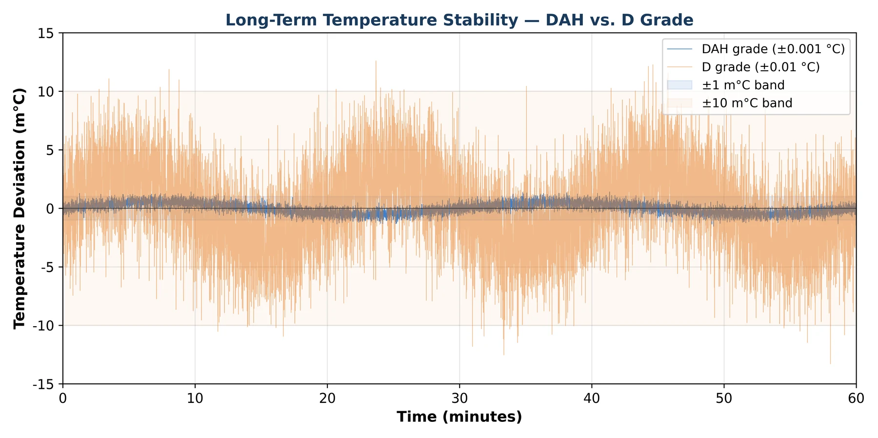
High-resolution stability such as ±0.001 °C is possible only when the entire thermal stack is designed for that requirement. The controller grade is important, but it does not replace good sensor placement, low thermal gradients, adequate hot-side dissipation, low-noise wiring, and load-specific compensation.
1. One-Sentence Definition
A TEC controller reads a temperature sensor, compares the measured temperature with a setpoint, applies loop compensation, and delivers regulated bidirectional current to a thermoelectric cooler so the controlled object can be heated or cooled automatically.
In control-system terms, a TEC controller is a thermal servo amplifier. The plant is slow, nonlinear, and strongly dependent on mechanical assembly quality. That is why a successful TEC design requires both an appropriate controller and a well-designed thermal path.
2. TEC Controller vs. TEC Driver vs. Discrete Op-Amp Loop
Engineers often compare three approaches: a dedicated TEC controller module, an open-loop TEC power driver, or a discrete analog loop built from op-amps, power stages, and passives. The right choice depends on required stability, development schedule, engineering resources, available board area, and production risk.
| Criterion | Dedicated TEC Controller Module | Open-Loop TEC Driver | Discrete Op-Amp / Custom PID Loop |
|---|---|---|---|
| Feedback | Closed-loop temperature regulation | No internal temperature loop; host system must close the loop | Closed-loop, but the loop must be designed and validated by the system engineer |
| Temperature stability | Controller-grade dependent; high-end systems can reach millidegree-level stability when the thermal design supports it | Depends on host firmware, ADC/DAC resolution, sensor design, power stage, and tuning | Achievable, but requires detailed analog compensation and careful layout |
| Prototype time | Fastest when used with an evaluation board and the actual thermal load | Requires firmware, characterization, and safety-limit implementation | Requires op-amp selection, compensation design, power layout, and repeated tuning |
| EMI control | Shielded ATI modules help reduce coupling into nearby analog, optical, and RF circuitry | Depends on external layout, filtering, shielding, and switching topology | Depends heavily on PCB layout, grounding, filtering, and enclosure design |
| Compensation | External compensation components or Auto-PID on supported families | Software control loop in the host processor | Fixed passives unless the board is designed for adjustment |
| Best fit | Production systems that need repeatable temperature regulation with lower design risk | Systems that already have a capable controller, acceptable stability margin, and sufficient firmware resources | Specialized instruments where the engineering team wants full analog control and accepts longer development time |
Design takeaway: If temperature stability is a product requirement rather than a laboratory convenience, validate a dedicated TEC controller with the real TEC, load, sensor, and heatsink before finalizing the mechanical and electrical design.
3. Thermal Physics Behind TEC Control
3.1 The Peltier Effect
When current flows through thermoelectric junctions, heat is absorbed on one side of the TEC and released on the other side. Reversing current direction reverses the heat-pumping direction. This makes the TEC useful for systems that need active cooling, active heating, or both.
A simplified cold-side heat-flow expression is:
Qc = α · I · Tc − 1/2 · I² · RTEC − K · ΔT
- α · I · Tc is the useful Peltier heat-pumping term.
- 1/2 · I² · RTEC represents Joule heating inside the TEC, which increases rapidly with current.
- K · ΔT represents conductive heat leakage from the hot side back to the cold side.
The hot side must reject the load heat plus electrical losses. A practical hot-side estimate is:
Qh ≈ Qc + PTEC electrical + Pcontroller losses
This is why heatsink design is not optional. If the hot side is undersized, the TEC may draw current correctly while the controlled object still fails to reach the setpoint.
3.2 Thermal–Electrical Analogy
Thermal systems are easier to analyze when mapped to familiar electrical concepts. Temperature difference is analogous to voltage, heat flow to current, thermal resistance to resistance, and thermal mass to capacitance.
| Electrical Concept | Thermal Concept | Typical Unit | Control Meaning |
|---|---|---|---|
| Voltage | Temperature difference | °C or K | Driving potential for heat flow |
| Current | Heat flow | W | Rate of energy transfer |
| Resistance | Thermal resistance, Rth | °C/W | Opposition to heat transfer |
| Capacitance | Thermal mass, Cth | J/°C | Stored thermal energy |
| RC time constant | τth = Rth × Cth | s | How quickly the load responds to heat input or removal |
The thermal time constant determines how aggressive the control loop can be. A small laser package may have a time constant of a few seconds, while a PCR block or larger test fixture may respond over tens of seconds or minutes. Compensation values that work for one load can oscillate or respond too slowly in another.
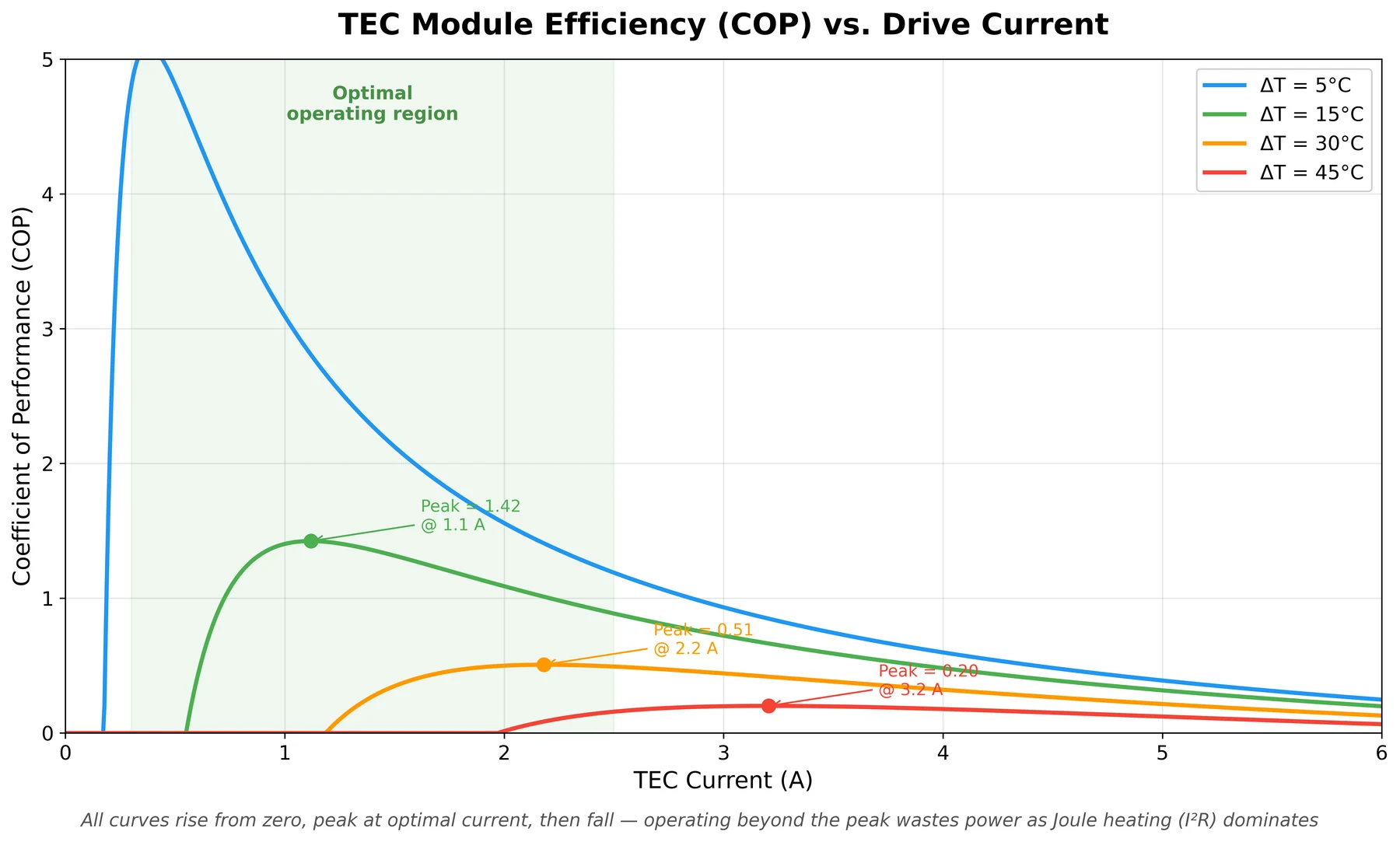
3.3 Coefficient of Performance and TEC Sizing
TEC efficiency is commonly described by coefficient of performance (COP):
COP = Qc / Pelectrical
For many TEC applications, COP is highest at a moderate fraction of the TEC maximum current. As current increases, Joule heating grows as I²R and eventually dominates the useful heat-pumping term. A TEC that is continuously operated near its maximum current usually runs hot, wastes power, and shortens system margin.
4. TEC Controller System Architecture
A TEC controller is more than a power stage. It combines a temperature setpoint input, sensor-feedback path, error amplifier, compensation network, bidirectional output stage, output filtering, protection features, and monitoring outputs.
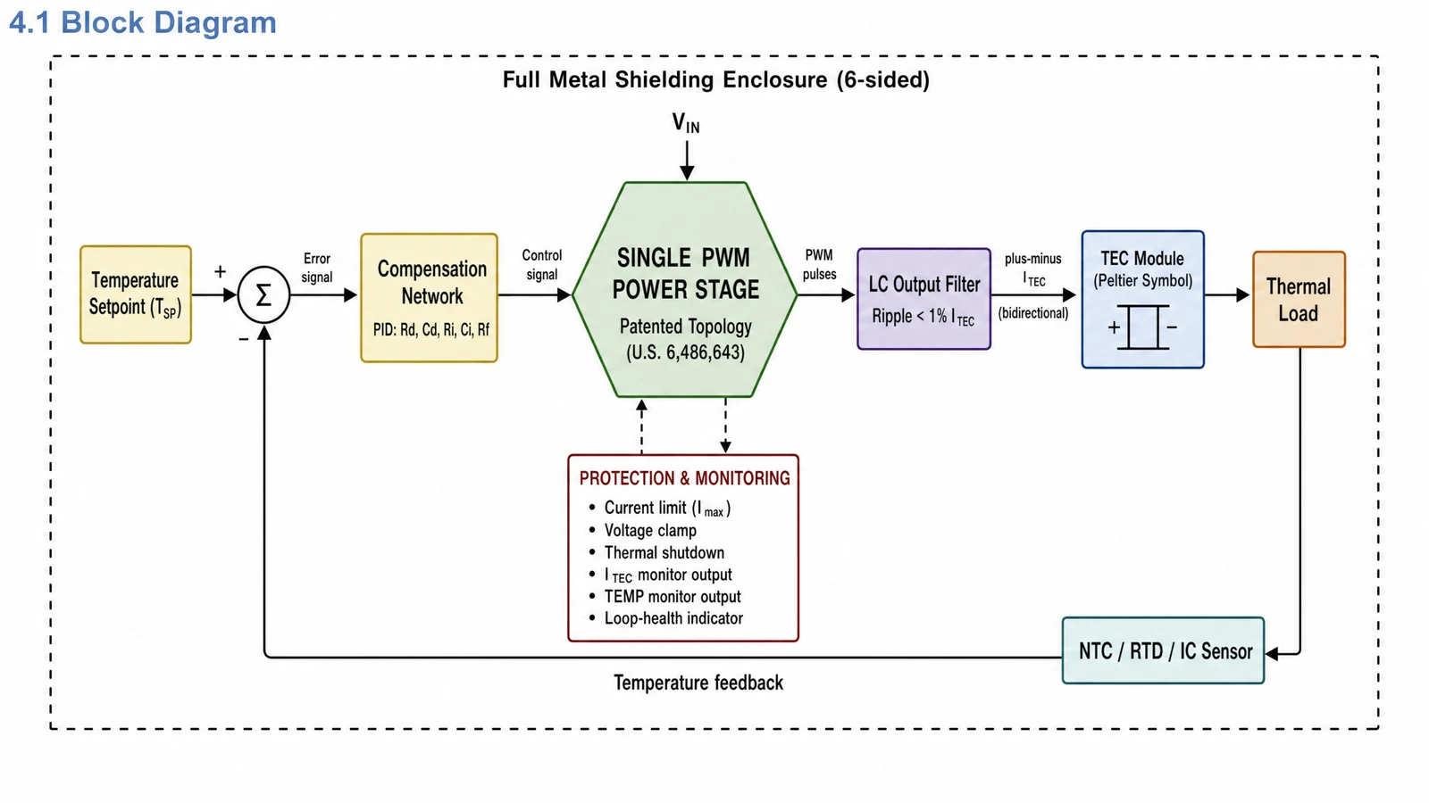
4.1 Main Signal Path
- Temperature setpoint: A voltage, DAC output, potentiometer setting, or system command that represents the target temperature.
- Temperature sensor: Typically an NTC thermistor, RTD, or IC temperature sensor mounted close to the controlled object.
- Error amplifier: Compares the sensor signal with the setpoint and generates an error signal.
- Compensation network: Shapes proportional, integral, and derivative behavior so the loop is stable for the thermal plant.
- Power stage and output filter: Deliver controlled current to the TEC while limiting unwanted ripple and electrical noise.
- TEC and thermal load: Convert electrical power into heat flow; current direction determines heating or cooling.
4.2 Protection and Monitoring
Protection and monitor functions vary by product family, but common TEC-controller features include current limiting, voltage limiting, thermal shutdown, temperature monitor output, TEC-current monitor output, and status or fault indication. These features help the system detect conditions such as an undersized TEC, failed heatsink, wiring error, sensor problem, or loop saturation.
| Function | Purpose | Engineering Benefit |
|---|---|---|
| Current limit | Caps TEC current at a defined maximum | Helps protect the TEC and load during transients or faults |
| Voltage limit | Restricts TEC output voltage | Prevents excessive TEC stress and helps handle abnormal load conditions |
| Thermal shutdown | Disables or limits output if the controller overheats | Reduces risk of cascade failure |
| Temperature monitor | Provides an analog representation of measured temperature | Allows the host system to log and verify regulation |
| TEC current monitor | Reports TEC operating current | Helps confirm operating point and detect saturation |
| Loop or fault status | Indicates abnormal regulation conditions | Supports diagnostics during startup, production test, and field service |
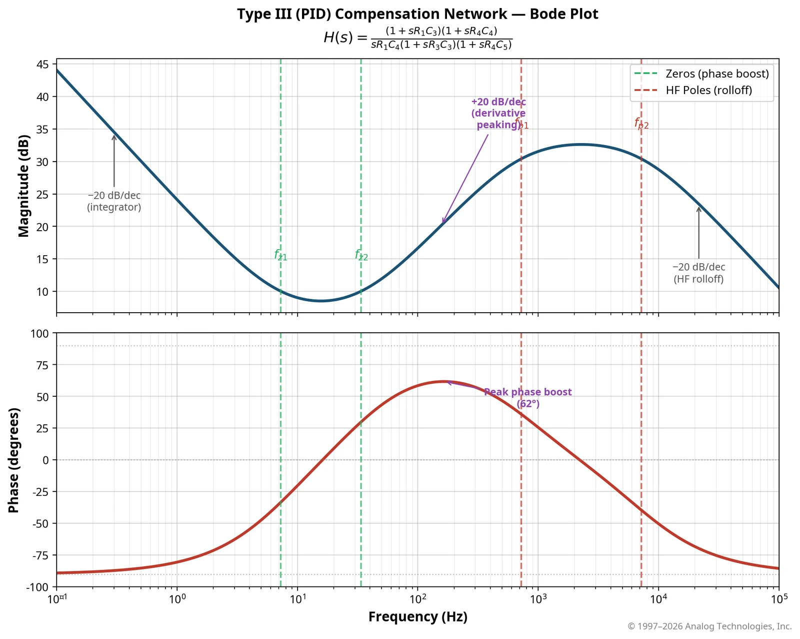
5. PID Compensation for Thermal Loads
A thermal load behaves like a low-pass plant with one or more time constants. To regulate temperature without steady-state error and without oscillation, the controller compensation must provide enough low-frequency gain, enough phase margin, and enough damping for the actual mechanical assembly.
5.1 Why PID Compensation Is Used
- Proportional action corrects temperature error immediately, but high proportional gain can create overshoot or oscillation.
- Integral action removes steady-state error by accumulating error over time. Too much integral action can cause slow oscillation.
- Derivative action adds predictive damping by responding to rate of change. Excessive derivative action can amplify sensor noise.
5.2 ATI External Compensation Components
Many ATI analog TEC controllers use external compensation components so the loop can be matched to the real thermal load. This is important because the thermal plant includes the TEC, load, sensor, thermal interface materials, heatsink, airflow, and enclosure.
| Component | Primary Role | Effect of Increasing the Value | Engineering Caution |
|---|---|---|---|
| Rd | Derivative gain | Increases high-frequency damping and response | Too much can increase noise sensitivity |
| Cd | Derivative time constant | Extends derivative action to lower frequencies | Must be matched to sensor and load delay |
| Ri | Integral gain setting | Changes low-frequency correction strength | Incorrect values can cause slow oscillation or offset |
| Ci | Integral time constant | Slows or stabilizes integral action | Too slow may increase settling time |
| Rf | Overall loop gain | Higher gain tightens regulation but reduces stability margin | Verify with a step response on the real system |
5.3 Why Thermal PID Is Harder Than Electrical PID
| Challenge | Electrical Loop | Thermal Loop |
|---|---|---|
| Dominant time constant | Microseconds to milliseconds | Seconds to minutes |
| Iteration time | Fast measurements | Each tuning step may take several minutes |
| Plant variation | Usually component-tolerance driven | Strongly affected by thermal interface, mounting pressure, airflow, insulation, and ambient conditions |
| Sensor delay | Often negligible | Sensor epoxy, placement, and thermal mass can add delay |
| Nonlinearity | Often manageable over a small range | TEC COP, ΔT, airflow, and contact resistance can change significantly with operating point |
6. ATI Implementation Features
ATI TEC controllers are designed as practical building blocks for OEM thermal-control systems. The features below should be evaluated at the model level, because exact voltage, current, package, control-interface, sensor, and protection details vary by product family.
6.1 Closed-Loop Analog Control
Many ATI TEC controller modules implement the control loop in analog circuitry. This allows the TEC controller to regulate temperature without requiring the host processor to run a real-time control loop. The host system can still set the target temperature and monitor status, but the thermal regulation is handled locally by the controller.
6.2 Patented Single-PWM TEC-Control Architecture
ATI’s TEC-control portfolio is associated with U.S. Patent 6,486,643 B2 for single-PWM TEC-control architecture. The practical benefit is a compact, efficient controller approach that can support bidirectional TEC current in applicable product families. Engineers should always confirm the exact topology and operating limits in the datasheet for the selected model.
6.3 Shielded Module Construction
TEC controllers often switch significant current near laser drivers, photodetectors, precision ADCs, and low-noise analog circuits. Metal shielding and careful filtering help reduce electromagnetic coupling. Final EMI performance, however, is a system-level result and should be verified in the customer’s PCB, enclosure, cabling, and grounding environment.
6.4 User-Tunable Compensation
External compensation components allow the control loop to be tuned for the real thermal load instead of a generic load assumption. This is especially important when sensor mounting, TEC contact pressure, thermal epoxy, heatsink airflow, or enclosure design can vary between prototypes and production units.
6.5 Auto-PID on Supported Families
Supported ATI controller families include Auto-PID versions that can characterize the thermal plant and configure compensation automatically. Auto-PID can be useful when load variation is high, tuning time is limited, or field deployment requires a repeatable tuning method. For ultra-low-disturbance systems, engineers should evaluate whether the Auto-PID test process is acceptable for the application.
6.6 Evaluation Boards
Evaluation boards are the fastest way to validate a TEC controller with the actual load. A good evaluation should use the real TEC module, sensor, heatsink, mechanical stack-up, wiring, insulation, and ambient conditions. The goal is not only to reach the setpoint, but to measure settling time, overshoot, current margin, hot-side temperature, stability, and fault behavior.
- TECEV104 — evaluation platform for several compact ATI TEC controller families.
- TEC28V15AEV1 / TEC28V15AEV2 — evaluation platforms for higher-current TEC18V / TEC28V controller families.
- TEC14MEV1.0 — evaluation platform for micro TEC controller designs.
6.7 Product Span
ATI offers TEC controller families covering compact low-voltage modules, laser-diode temperature stabilization, micro SMT controllers, higher-current controllers, and Auto-PID options. This allows engineers to start with the supply voltage, TEC current, TEC voltage, stability requirement, package, and tuning method, then narrow the selection to the correct family and SKU.
7. Error Budget and Real-World Stability
Temperature stability is often quoted as a controller specification, but the measured system stability is the sum of many electrical, thermal, and mechanical error sources. In high-stability systems, the controller may not be the dominant error source.
| Error Source | Typical Impact | How to Reduce It |
|---|---|---|
| Sensor tolerance and calibration | Absolute temperature error | Use precision sensors, calibrate the sensor/load assembly, and verify against a traceable reference when required |
| Sensor self-heating | Sensor reads warmer than the load | Use low excitation current and a suitable sensor resistance |
| Sensor-to-load gradient | Controlled sensor temperature differs from actual load temperature | Mount the sensor directly on the controlled object and minimize thermal resistance |
| Ambient variation | Changes hot-side temperature and heat leakage | Improve insulation, airflow control, and heatsink margin |
| TEC ripple current and electrical noise | Can modulate temperature or inject noise into nearby circuits | Use proper filtering, grounding, shielding, and short sensor wiring |
| Controller noise and reference drift | Limits fine setpoint resolution and repeatability | Select the appropriate controller grade and provide clean supply and layout conditions |
| Compensation mismatch | Overshoot, oscillation, or slow settling | Tune compensation with the actual thermal load and validate over operating extremes |
Engineering takeaway: For a millidegree-class system, specify the controller grade and the complete measurement method. Include sensor type, calibration method, ambient range, load condition, heatsink temperature, measurement bandwidth, and stability time window.
8. Reliability and Long-Term Stability
8.1 Sensor Aging
NTC thermistors, RTDs, and semiconductor temperature sensors have different aging, packaging, and calibration behavior. For long-life systems, select a sensor package appropriate for the temperature range and environment. Precision applications should include calibration or periodic verification in the maintenance plan.
8.2 TEC Stress from Thermal Cycling
Each heat-cool cycle stresses the TEC module, its solder joints, and the mechanical stack. Large temperature swings, high current, rapid cycling, and poor hot-side dissipation can reduce lifetime. For best reliability, avoid operating the TEC at unnecessary ΔT, avoid continuous operation near maximum current, and use a TEC module with adequate margin.
8.3 Condensation Below Dew Point
When the controlled surface is cooled below the ambient dew point, moisture can condense on the load, TEC, sensor, PCB, or optics. Condensation can cause corrosion, leakage current, optical contamination, and reliability failures. Applications that operate below dew point should use dry gas, sealing, conformal protection, dew-point monitoring, or setpoint limits.
8.4 Controller Derating and Thermal Management
The TEC controller also dissipates heat. Controller power loss depends on TEC current, supply voltage, output voltage, topology, efficiency, PCB layout, airflow, and mounting. Verify controller temperature at the worst-case ambient, maximum load, and maximum expected TEC current. Add airflow, heatsinking, copper area, or mechanical thermal paths as required by the selected datasheet.
9. Best Practices and Common Mistakes
Do
- Measure the real heat load before selecting the TEC and controller.
- Size the TEC with current, voltage, ΔT, and hot-side thermal margin.
- Mount the sensor on the controlled object, not on the heatsink.
- Validate compensation with the real TEC, load, heatsink, and enclosure.
- Use short, shielded, or carefully routed sensor wiring in noisy systems.
- Check setpoint accuracy, stability, settling time, overshoot, and fault behavior.
- Verify hot-side dissipation at worst-case ambient temperature.
Do Not
- Do not assume default compensation values are production-ready.
- Do not run the TEC near maximum current continuously unless the datasheet and thermal design support it.
- Do not ignore sensor placement or thermal gradients.
- Do not cool below dew point without moisture control.
- Do not rely on controller specifications alone to guarantee system stability.
- Do not finalize the PCB before testing the complete thermal stack.
- Do not treat the heatsink as a secondary component; it is part of the control loop.
10. Applications
TEC controllers are used where repeatable temperature regulation improves optical, electrical, biological, or measurement performance. The table below gives representative use cases and starting points for discussion; final model selection should be based on current, voltage, stability, package, sensor, compensation, and datasheet limits.
| Application | Why Temperature Control Matters | Typical Stability Target | Representative ATI Starting Point |
|---|---|---|---|
| DFB, VCSEL, and pump laser modules | Laser wavelength, efficiency, and output power depend strongly on temperature | ±0.001 to ±0.01 °C | TEC5V6A-DAH or related DAH-grade controller |
| Photodetectors and APDs | Dark current, gain, and noise change with temperature | ±0.01 °C class | TEC5V4A-DA or TEC5V4A-D, depending on requirement |
| Optical spectrum analyzers and filters | Optical alignment, grating behavior, and filter response can drift with temperature | ±0.005 °C class | TECA1 or DAH-grade controller family |
| Medical diagnostics and PCR blocks | Reaction rates and repeatability depend on controlled thermal cycling | Application dependent, often ±0.1 °C class | TEC18V / TEC28V family, depending on load power |
| IR sensors and cooled cameras | Detector dark current and image noise improve with controlled sensor temperature | ±0.05 to ±0.1 °C class | TEC14M or TEC5V family, depending on power and package |
| Semiconductor test fixtures | DUT parameters must be characterized at known temperatures | ±0.01 to ±0.1 °C class | TEC18V15A / TEC28V15A family |
| Frequency references and oscillators | Frequency drift is temperature dependent | ±0.001 to ±0.01 °C class | DAH-grade controller family |
| LiDAR optical assemblies | Transmitter wavelength and receiver filter alignment affect link performance | ±0.01 °C class | TEC5V4A-D / TEC5V6A family |
| Quantum cascade lasers | Mid-IR wavelength and output behavior are temperature sensitive | ±0.005 °C class or tighter | TEC18V / TEC28V family as required by load power |
11. Product Selection Guide
Start selection from the thermal requirement, not from the controller part number. Define the controlled object, target temperature, ambient range, heat load, TEC current and voltage, stability requirement, sensor type, board area, and tuning method. Then choose the controller family.
| Family / Example Part | Input Supply Class | Output Current Class | Typical Use | Selection Notes |
|---|---|---|---|---|
| TEC14M series | Low-voltage micro applications | Up to a few amperes, model dependent | Compact SMT thermal-control designs | Use when footprint is the primary constraint; confirm package and compensation details. |
| TEC5V4A-D / DA / DAH | 5 V class | 4 A class | Laser diode, detector, and compact optical modules | Choose D, DA, or DAH based on stability and setpoint-accuracy requirements. |
| TEC5V6A-D / DA / DAH | 5 V class | 6 A class | Higher-current laser and photonics packages | Use when the 4 A family does not provide sufficient current margin. |
| TECA1 family | Compact precision-control applications | Model dependent | High-precision optical and instrumentation loads | Confirm sensor interface, precision grade, and exact voltage/current limits. |
| TEC18V15A family | Wide supply, higher-power applications | 15 A class | Thermal blocks, semiconductor fixtures, larger optical assemblies | Use when the load requires higher current or output voltage than 5 V families can provide. |
| TEC18V15A Auto-PID versions | Wide supply, higher-power applications | 15 A class | Systems where tuning time or load variation is important | Evaluate Auto-PID behavior on the real load and verify disturbance tolerance. |
| TEC28V15A family | Higher output-voltage applications | 15 A class | Higher-power TEC modules and larger ΔT designs | Use when higher TEC output-voltage capability is required. |
| TEC28V15A Auto-PID versions | Higher output-voltage applications | 15 A class | High-power systems with automated tuning needs | Confirm package, Auto-PID process, and power-stage thermal limits. |
Precision Grade Guidance
- D grade: General closed-loop temperature control where moderate accuracy and stability are acceptable.
- DA grade: Higher-precision systems that need tighter setpoint accuracy and lower control error.
- DAH grade: Ultra-stable optical, laser, or instrumentation applications where millidegree-class performance is required and the full thermal system is designed accordingly.
Fast Selection Flow
- Define target temperature, stability requirement, ambient range, heat load, and response time.
- Select the TEC module from Qmax, Imax, Vmax, ΔT, size, and reliability requirements.
- Choose a controller family that supports the required input supply, TEC current, and TEC output voltage with margin.
- Select D, DA, or DAH grade based on measurement and stability requirements.
- Decide whether manual compensation or Auto-PID is the better tuning method.
- Validate with an ATI evaluation board and the real thermal assembly before production release.
12. Worked Example: DFB Laser at 25.000 °C
This example shows how a TEC controller selection is made from the thermal load rather than from a generic current rating.
| Parameter | Example Value | Engineering Reasoning |
|---|---|---|
| Target temperature | 25.000 °C | DFB wavelength stabilization requirement |
| Required stability | ±0.001 °C class | Requires DAH-grade controller and careful thermal design |
| Estimated cooling load | 0.8 W | Laser dissipation plus parasitic heat load |
| Selected TEC module | 3 A Imax class | Allows steady-state operation around a moderate current fraction |
| Expected TEC current | Approximately 0.8 A | Provides margin while avoiding continuous operation near Imax |
| Measured thermal time constant | Approximately 4 s | Measured from the load step response |
| Controller starting point | TEC5V6A-DAH class | Provides current margin and high-stability control grade |
| Sensor | Precision NTC thermistor mounted on the laser package | Sensor placement minimizes thermal gradient to the controlled object |
For this load, a first compensation estimate would place crossover well below the 4 s thermal pole. The actual values should then be tuned and verified on an evaluation board using the same laser package, TEC module, sensor mounting method, heatsink, airflow, and enclosure used in production.
| Component | Example Value | Purpose |
|---|---|---|
| Rd | 100 kΩ | Derivative gain starting point |
| Cd | 330 pF | Derivative time-constant starting point |
| Ri | 470 kΩ | Integral gain starting point |
| Ci | 10 nF | Integral time-constant starting point |
| Rf | 47 kΩ | Overall loop-gain starting point |
13. Troubleshooting Quick Reference
| Symptom | Likely Cause | Corrective Action |
|---|---|---|
| Slow oscillation around the setpoint | Compensation mismatch, crossover too high, excessive integral action, or sensor delay | Reduce loop gain, retune compensation, improve sensor mounting, or evaluate Auto-PID |
| Steady-state offset | Insufficient integral action, calibration error, sensor placement error, or output saturation | Check sensor calibration and placement; adjust integral compensation; verify current and voltage headroom |
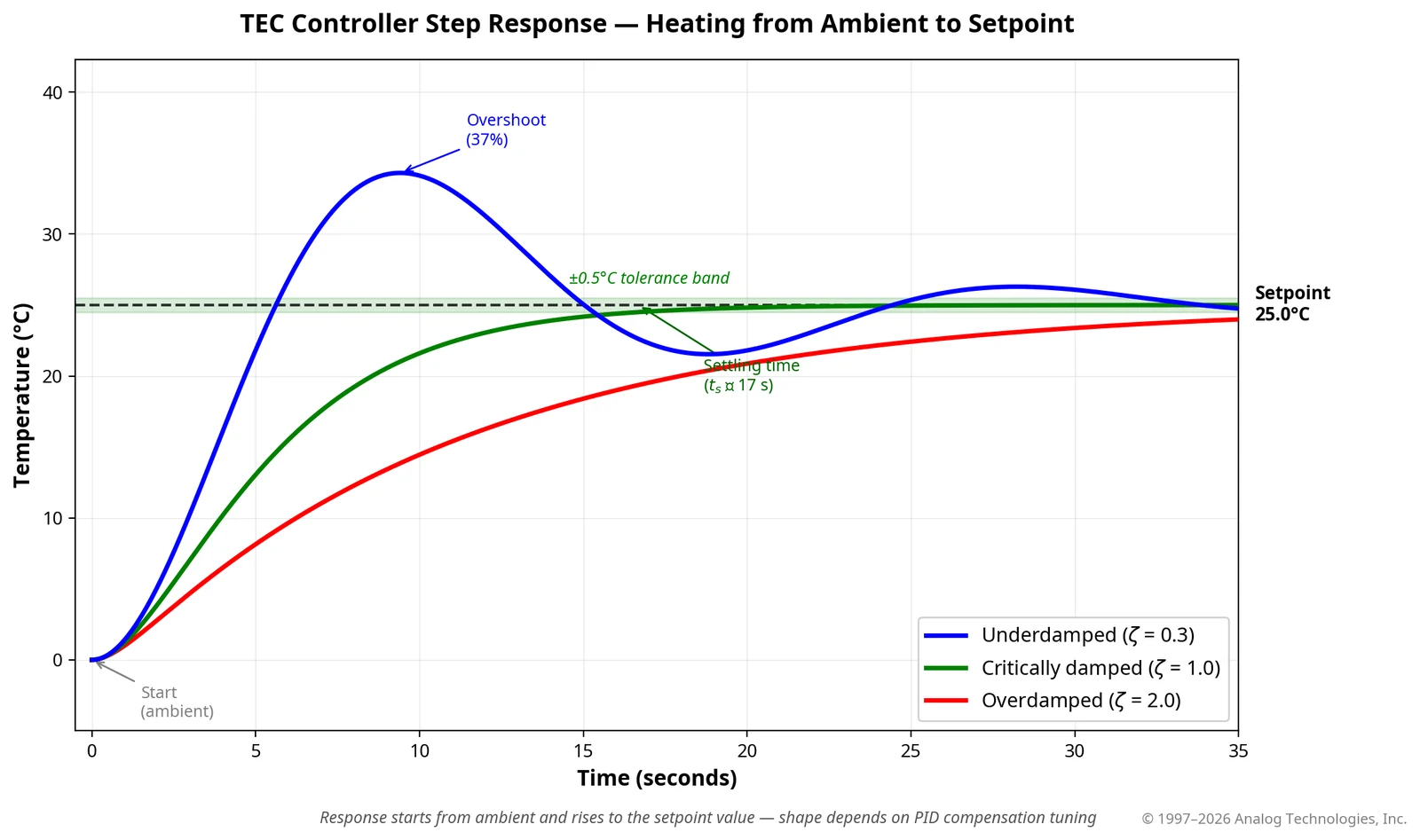
| Large overshoot after setpoint change | Loop too aggressive or insufficient damping | Reduce overall gain, increase damping, and verify with step-response testing |
| Very slow settling | Overdamped compensation, low loop gain, large thermal mass, or undersized TEC | Adjust compensation, confirm TEC sizing, and verify hot-side thermal resistance |
| Controller output saturates | TEC undersized, hot side too warm, load heat too high, or setpoint beyond capability | Use a larger TEC, improve heatsinking, lower heat load, or revise the setpoint requirement |
| High-frequency noise on temperature monitor | EMI coupling, long sensor leads, poor grounding, or inadequate filtering | Use shielded routing, proper grounding, short sensor leads, and a shielded controller module |
| Stable at room temperature but unstable at low or high ambient | Thermal plant changes with operating point | Tune and verify compensation across the full temperature and ambient range |
| Condensation on cold surfaces | Setpoint below ambient dew point | Seal the cold zone, add dry gas, use dew-point monitoring, or limit the setpoint |
| TEC current present but no cooling | Reversed polarity, poor thermal contact, failed TEC, or hot-side thermal failure | Check TEC polarity, mounting pressure, interface material, TEC health, and heatsink temperature |