TEC Controllers
Thermo-Electric Coolers, also known as Peltier coolers, provide both cooling and heating by reversing current flow. Analog Technologies Inc (ATI) TEC controllers precisely regulate TEC current direction and amplitude to maintain stable temperature in demanding thermal control applications.
With more than 21 years of TEC controller design experience, ATI has developed a patented single-PWM output-stage architecture that improves power efficiency while reducing component count, PCB area, and system cost compared with conventional dual-PWM designs. ATI offers a broad range of TEC controllers for applications requiring high precision, high efficiency, compact size, and reliable long-term temperature regulation.
Filter and compare TEC controller products
Precision thermoelectric (Peltier) controllers for laser diodes, photonic devices and scientific equipment. Filter by Max Current, Input Voltage, Package Type and Stability Class, then compare output voltage, features, datasheets, price and stock.
Showing 1–12 of 87 resultsSorted by price: low to high
| Image | SKU | Max. Current | Input Voltage | Max. Output Voltage | Temp Stability | Features | Datasheet | Price | Stock | Action |
|---|---|---|---|---|---|---|---|---|---|---|
 |
TEC14M5V3R5AS | 3.5A | 2.7V ~ 5.5V | ±VVPS | 0.001°C | Bipolar | $52.00 | 35 | ||
 |
TECA1-3V-1.3V-D | 2.5A | 3.3V | ±1.3V | ≤5mV | Bipolar | $79.00 | 4 | ||
 |
TECA1-5V-2.5V-D-OP | 2.5A | 5V | ±2.5V | ≤5mV | Bipolar | $79.00 | 58 | ||
 |
TECA1-5V-2.5V-S-OP | 2.5A | 5V | ±2.5V | ≤5mV | Bipolar | $79.00 | Out of Stock | ||
 |
TECA1-5V-3V-D | 2.5A | 5V | ±3V | ≤5mV | Bipolar | $79.00 | 7 | ||
 |
TECA1-5V-5V-D | 2.5A | 5V | ±5V | ≤5mV | Bipolar | $79.00 | 29 | ||
 |
TECA1-5V-4V-D | 2.5A | 5V | ±4V | ≤5mV | Bipolar | $79.00 | 5 | ||
 |
TECA1-5V-3.5V-D | 2.5A | 5V | ±3.5V | ≤5mV | Bipolar | $79.00 | Out of Stock | ||
 |
TECA1-5V-2.5V-D | 2.5A | 5V | ±2.5V | ≤5mV | Bipolar | $79.00 | 106 | ||
 |
TECA1-5V-2V-D | 2.5A | 5V | ±2V | ≤5mV | Bipolar | $79.00 | 36 | ||
 |
TECA1-3V-3V-D | 2.5A | 3.3V | ±3V | ≤5mV | Bipolar | $79.00 | 9 | ||
 |
TECA1-3V-2.5V-D | 2.5A | 3.3V | ±2.5V | ≤5mV | Bipolar | $79.00 | 17 |
Our Delivery Promise
Fast, flexible fulfillment from San Jose, California, USA for prototype, pilot, and production builds.
- Fast in-stock shipping — In-stock orders ship within 1–2 business days after confirmation and quality check.
- Worldwide shipping — Shipped from San Jose to customers worldwide.
- Flexible carrier options — UPS, FedEx, DHL, USPS, freight forwarders, or your preferred logistics partners.
- Clear shipment visibility — Tracking provided after dispatch to support your receiving and production planning.
TEC controller family comparison
Compare ATI TEC controller platforms by drive current, supply rail, output voltage, precision/stability, package, sensor support, and compensation — then confirm exact SKU limits in the datasheet.
| Controller family | Max current | Input voltage | TEC output voltage | Precision / stability | Package & size | Sensor support | Loop tuning / compensation |
|---|---|---|---|---|---|---|---|
| TECA1 Compact Low-Current TECA1-xV-xV compact series | 2.5A | 3.3V / 5V | ±1.3V to ±5V, model dependent | ≤5mV standard ≤0.5mV high precision | DIP / select SMT25.4 × 19.9 × 4.5mm class | Thermistor | External compensation |
| TECA1LD Built-in Compensation TECA1LD-xV-xV compact series | 2.5A | 3.3V / 5V | ±1.3V to ±5V, model dependent | ≤5mV standard ≤0.5mV high precision | DIP / select SMT25.4 × 19.9 × 4.5mm class | Thermistor | Built-in compensation networkDesigned for easier integration |
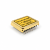
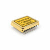
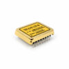
| TEC14M Micro SMT TEC14M5V3R5AS | 3.5A | 2.7V to 5.5V | Up to ±VVPS | 0.001°C class | Micro SMT14 × 14 × 2.2mm | Thermistor | Integrated compact controller platform |
| TEC5V High-Current 5V TEC5V4A / TEC5V6A series | 4A / 6A | 5V | ±4.8V (4A) / ±4.7V (6A) | ≤5mV standard ≤2mV precision ≤0.5mV high precision | DIP25.4 × 19.9 × 4.5mm class | Thermistor | External compensation |
| TEC9V7A High-Power 9V TEC9V7A family | 7A | 5.5V to 9V | ±7.2V | <±0.001°C class | DIP / SMT35.7 × 35.7 × 7.2mm class | Thermistor, RTD, or IC sensor | Manual tuning; Auto-PID optionalAPID variant available |
| TEC12V High-Power 12V TEC12V6A / TEC12V9A family | 6A / 9A | 5.5V to 12V | ±9.6V | <±0.001°C class | DIP / SMT35.7 × 35.7 × 7.2mm class | Thermistor, RTD, or IC sensor | Manual tuning; Auto-PID optionalAPID variant available |
| TEC18V High-Power 18V TEC18V6A / TEC18V10A / TEC18V15A family | 6A / 10A / 15A | 5.5V to 18V | ±14.4V to ±18V, model dependent | <±0.001°C class | DIP / SMT35.7 × 35.7 × 7.2mm class | Thermistor, RTD, or IC sensor | Manual tuning; Auto-PID optionalAPID variant available |
Explanation:
- Precision values for TECA1, TECA1LD, and TEC5V are control-loop error classes (|VTEMP−VTEMPSP|), not direct temperature-stability values; TEC14M, TEC9V, TEC12V, and TEC18V values are temperature-stability classes.
- Listed families are intended for bipolar heating and cooling control.
- High-power families may include DIP/SMT, NCO, and Auto-PID configuration options; confirm the exact suffix and limits in the datasheet.
For a more detailed family comparison, read the family comparison white paper. For full specifications, see the individual product pages above.
Features & Advantages of ATI TEC Controllers
Why choose ATI TEC controllers? Because they help engineers achieve stable, efficient thermoelectric temperature control with less design risk — through patented power-stage topology, tunable PID compensation, full EMI shielding, evaluation board support, and long-term product continuity.
- Patented Single-PWM Topology — Protected under U.S. Patent 6,486,643 B2, ATI’s single-PWM power-stage topology delivers bidirectional TEC current efficiently while helping reduce switching losses, component count, PCB area, and system heat. ATI reports roughly 25% lower component cost, 35% smaller PCB footprint, and >92% typical efficiency measured on TEC18V15A.
- Auto-PID Self-Tuning Compensation — Selected ATI TEC controllers automatically evaluate the thermal load and configure PID compensation in approximately 60 seconds, reducing manual tuning time. Recommended models include TEC18V15ADAPID for DIP integration and TEC28V15ASAPID for higher-voltage SMT applications.
- Full Bidirectional EMI Shielding — ATI shielded TEC controller modules use a six-sided full metal enclosure to help reduce capacitive, inductive, radiated, and conducted EMI coupling. This is especially valuable when the TEC controller is placed near laser drivers, photodetectors, precision ADCs, optical sensors, and other noise-sensitive analog circuits.
- User-Tunable Compensation Network — ATI TEC controllers expose five compensation components — Rd, Cd, Ri, Ci, and Rf — so engineers can tune the PID loop to the actual thermal load instead of relying on one-size-fits-all compensation. LD-suffix variants, such as TECA1LD-xV-xV-D and TECA1LD-xV-xV-DAH, include an internal compensation network for plug-and-play use.
- Evaluation Boards for Fast Validation — ATI evaluation boards let engineers test the controller with the real TEC module, sensor, heatsink, and thermal load before final PCB release. Recommended platforms include TECEV104 for TEC5V4A, TEC5V6A, and TECA1 families; TEC28V15AEV1/EV2 for TEC18V15A and TEC28V15A series; and TEC14MEV1.0 for micro TEC controllers.
- Full Product Span from Micro to High Power — ATI offers TEC controllers from compact micro modules to high-current controllers, covering different input voltages, output currents, package styles, precision grades, and integration needs. Representative models include TEC14M5V3R5AS, TEC5V4A, TEC5V6A, TECA1 series, TEC18V15A, and TEC28V15A.
- Long-Term Product Continuity — Since 1997, no ATI TEC controller has been discontinued — every model introduced remains in active production. ATI also provides pin-compatible upgrade paths where available and direct engineering support, helping OEM customers reduce redesign risk and avoid unexpected end-of-life issues.
Read more about the features and advantages of ATI TEC controllers. For full specifications, see the individual product pages above.
Typical Applications of ATI TEC Controllers
Where are ATI TEC controllers used? Across photonics, imaging, test & measurement, medical diagnostics, and OEM thermal-control systems — wherever stable bidirectional heating and cooling, low-noise operation, and repeatable temperature regulation are required.
- Laser diode cooling & wavelength stabilization — DFB lasers, VCSELs, pump lasers, and QCL modules need stable package temperature to reduce wavelength drift, output-power variation, and spectral degradation. Typical starting models include TEC5V6A-DAH for compact laser modules and TEC18V15A / TEC28V15A for higher-power photonics packages.
- Photodetectors, APDs & optical receivers — Detector gain, dark current, and noise can drift with temperature. ATI TEC5V4A-DA helps stabilize photodetectors, APDs, SPAD modules, fiber-optic receivers, LiDAR receivers, and low-noise optical front ends.
- IR sensors & cooled imaging sensors — IR sensors, CCD cameras, CMOS sensors, and compact thermal-imaging modules use TEC cooling to reduce dark current, pixel noise, and temperature-related image drift. Typical starting models include TEC14M5V3R5AS and TEC5V4A-D.
- LiDAR & optical communication modules — Laser transmitters and optical transceivers benefit from stable TEC control to reduce wavelength drift across ambient temperature changes. TEC5V4A-DA and TEC5V6A-DA are practical starting choices for compact automotive LiDAR, datacom transceivers, and DWDM optical modules.
- Optical test & measurement instruments — Optical spectrum analyzers, wavelength meters, interferometers, OCXOs, FBG interrogators, and precision timing modules require stable internal laser, detector, or oscillator temperatures. TECA1-xV-xV-DAH and TEC5V6A-DAH are suitable high-stability options when paired with proper insulation, sensor placement, and compensation tuning.
- Semiconductor, sensor & battery test fixtures — Device-under-test fixtures, thermal plates, and battery-cell test setups need controlled heating and cooling during characterization or production screening. TEC18V15A is a common high-current starting model for these fixture-level applications.
- Medical diagnostics & life-science instruments — PCR blocks, ELISA incubators, sample holders, DNA sequencers, and diagnostic thermal stages depend on repeatable thermal profiles. TEC18V15A supports medium-size thermal loads where controlled bidirectional temperature regulation is required.
- Custom OEM thermal platforms — For application-specific thermal loads, sensors, and mechanical designs, ATI evaluation boards — TECEV104, TEC28V15AEV1/EV2, and TEC14MEV1.0 — help engineers validate the controller, TEC module, and compensation network with the actual thermal load before committing to a final PCB.
How to choose the right TEC controller
A practical workflow for matching a controller to a TEC module and application.
1. Define the temperature requirement
Identify the target temperature, stability, ambient range, and whether the load needs cooling, heating, or both.
2. Match TEC current and voltage
Select a controller with enough output current and voltage for the TEC module, with safe operating margin.
3. Choose the input-voltage family
Match the controller to the available system supply. ATI TEC controller families cover input voltages from 2.7 V to 24 V, spanning compact low-voltage to high-power applications.
4. Select the stability grade
Use D for general control, DA for higher precision, and DAH for ultra-stable laser or optical applications.
5. Check sensor placement
Mount the sensor directly on the controlled object to reduce delay, gradients, and temperature error.
6. Validate the full thermal system
Confirm the TEC, heatsink, sensor, controller, shielding, and compensation values work together under real operating conditions.
TEC controller FAQ
Common questions about selecting and using ATI TEC controllers.
What is the difference between a TEC controller and a TEC driver?
A TEC controller is a closed-loop system that reads temperature feedback and automatically adjusts TEC current to maintain a setpoint. A TEC driver is open-loop — it only delivers a commanded current and requires external logic or firmware to close the temperature loop. Use a controller when temperature accuracy matters; use a driver when an external MCU handles the regulation.
Can ATI TEC controllers both heat and cool?
Yes. ATI TEC controllers are bidirectional. They automatically reverse TEC current direction to heat or cool as needed to reach the temperature setpoint. No external polarity-switching circuit is required.
What temperature stability can ATI TEC controllers achieve?
Stability as fine as ±0.001 °C is achievable with DAH-grade controllers, such as the TEC5V6A-DAH, under specified conditions: load-matched compensation, a precision thermistor, good thermal isolation, and stable ambient temperature.
What is the difference between D, DA, and DAH precision grades?
D grade provides ≤5 mV setpoint accuracy, DA grade provides ≤2 mV, and DAH grade provides ≤0.5 mV. Higher grades use tighter-tolerance internal components and lower-noise voltage references. Choose the grade based on the required temperature stability — DAH is recommended for wavelength-critical laser, optical, and precision instrumentation applications.
What input-voltage and TEC-current ranges are available?
ATI TEC controller families cover input voltages from 2.7 V to 24 V, depending on the model family. The Micro TEC series operates at 2.7–5.5 V. The TEC5V series operates at 4.5–5.5 V. The TEC18V15A series operates at 5.5–18 V with up to 15 A TEC current and ±14.5 V output. The TEC28V15A series operates at 5.5–25 V with up to 15 A TEC current and ±20 V output. For higher-current applications, contact ATI engineering for custom solutions.
What temperature sensors are supported?
ATI TEC controllers support NTC thermistors, platinum RTDs, and semiconductor temperature ICs, depending on the model. NTC thermistors are commonly used for the highest resolution near 25 °C, while platinum RTDs are preferred for the best long-term stability.
When should I use Auto-PID instead of manual tuning?
Use Auto-PID controllers, such as the TEC18V15ADAPID or TEC28V15ASAPID, when the thermal load varies between units, the operating temperature range is wide, tuning time is limited, or field deployment requires fast setup. Use manual tuning with an evaluation board for fixed-load production systems where the lowest possible noise and repeatable final compensation values are required.
How do I choose compensation values such as Rd, Cd, Ri, Ci, and Rf?
Measure the thermal load's thermal time constant (τth) using a step-response test, then set the loop crossover frequency to approximately fc = 1 / (5–10 × τth). Use the ATI evaluation board that matches your controller family to adjust Rd, Cd, Ri, Ci, and Rf while monitoring the temperature response — refer to each product's datasheet for the correct evaluation board part number. ATI datasheets provide starting-point values for common load types.
How does ATI reduce EMI in TEC controller designs?
ATI shielded TEC controllers use a full six-sided metal enclosure to block capacitive, inductive, radiated, and conducted coupling paths. The shielding is bidirectional — it helps protect the controller from external noise and helps reduce switching-noise coupling into nearby sensitive circuits such as laser drivers, photodetectors, precision ADCs, and low-noise analog front ends.
How do I prevent condensation when cooling below the dew point?
When the controlled surface is cooled below the ambient dew point, moisture can condense and cause corrosion, electrical leakage, shorts, or optical contamination. Seal the cold zone in a hermetic or dry-gas-purged enclosure, add desiccant if the enclosure is not perfectly sealed, monitor humidity, and set a minimum temperature limit in the control logic to prevent cooling below the local dew point.