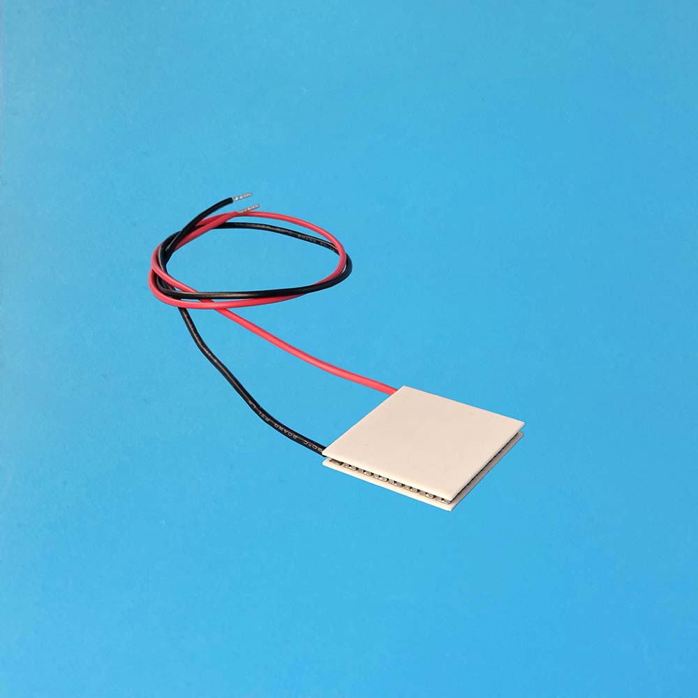
Thermoelectric coolers (TECs), also known as Peltier coolers, thermoelectric modules, or TEC modules, are versatile devices capable of generating both heating and cooling effects by applying an electric current, depending on its direction. When the current flows in one direction, one of the Peltier cooler plates heats up while the other cools down. Reversing the current causes the TEC plates to switch their thermal polarity.
TEC modules find applications in various fields, with a prime example being the precise temperature regulation of laser diode chips. This regulation ensures the emission of stable laser beams with a consistent wavelength and minimal optical noise.
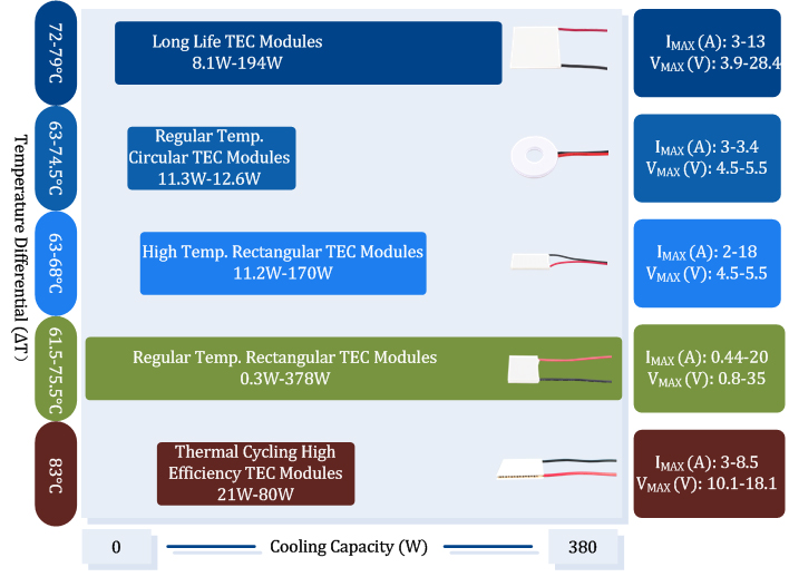
Selecting the Right TEC Modules
When designing a temperature regulation system based on TECs, choosing the appropriate TEC module is crucial. Here are some general guidelines:
1. TEC Lifespan: TECs have a limited lifespan, which can be measured by monitoring the relative change in their AC resistance. Once the AC resistance increases by 10%, the TEC is considered at the end of its useful life.
2. AC Resistance Measurement: To monitor the AC resistance, use specialized meters. We offer a dedicated meter (TH2810D) for this purpose.
3. Minimize Delta T: To enhance the overall system efficiency, known as the Coefficient of Performance (COP), it's crucial to minimize the temperature difference (delta T) between the two TEC plates.
4. Avoid Sheer Force: TEC modules are sensitive to sheer forces, which can lead to the breakage or cracking of the internal semiconductor elements.
5. Gentle Current Switching: When controlling TEC current, avoid hard switching methods that result in sudden temperature changes within the semiconductor elements.
6. Selecting Appropriate Mounting Methods: There are three commonly used methods for mounting TEC modules: compression with thermal grease, adhesive bonding, and soldering.
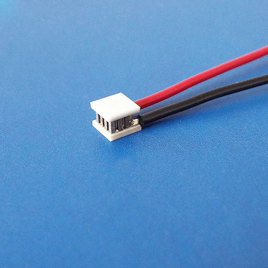
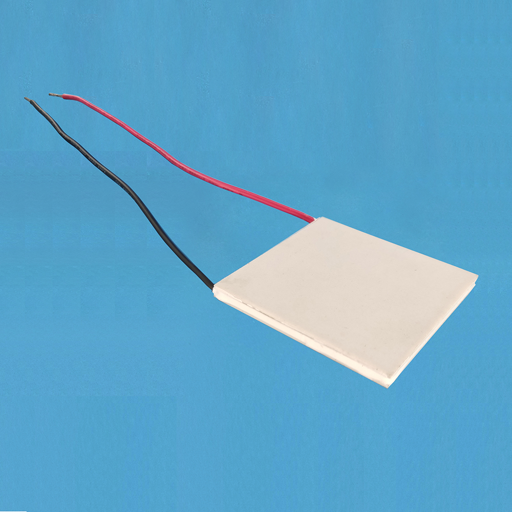
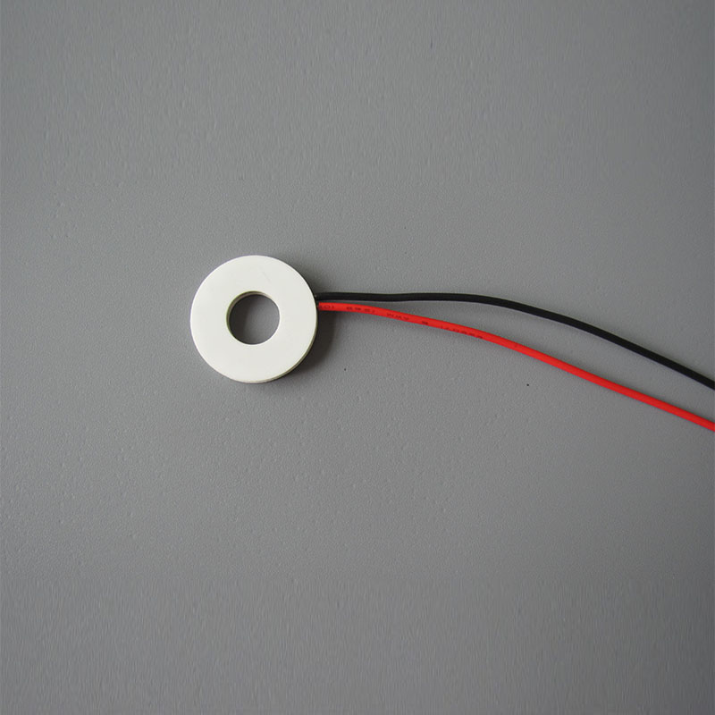
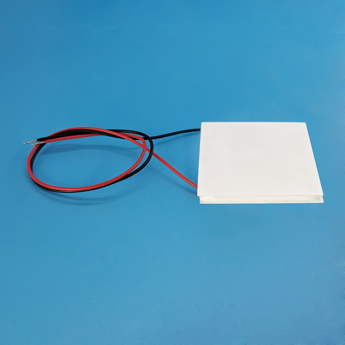
A: 1. Usually, when mounting the TEC module, you want to mount the side onto which the lead wires are soldered, to the heat sink, thus this side becomes the hot side. The other side becomes the cold side on which the target object is mounted. 2. The positive terminal of a TEC module is defined in such a way that when connecting it to a positive side of a voltage source, the TEC's cold side (as it was determined above) is cooled down.
A: The life expectancy is defined as the time when ACR (Alternating Current Resistance) is increased to 10%. A TEC's ACR can be measured by an LCR meter. The life time of a TEC module can be shortened by applying a full maximum voltage back and forth, i.e. to switch the polarity of the full maximum voltage applied to the TEC. For regular TEC modules, they can apply the full maximum voltage back and forth (switch the polarity) for up to 500 times. Besides, the number of times can be up to 3x10^7 times, the calculated MTBF was 125,000 hours.
A: TEC stands for Thermo-Electric Cooler and TEG stands for Thermo-Electric Generator. The former is a device that generates thermal cold and heat by feeding a current through a TEC; the latter is also a device that generates electrical voltage potential, and thus electrical current after adding an electrical load, by creating a thermal temperature difference between the 2 sides of the TEG. Generating thermal cold and heat from electrical current is called a Peltier Effect; Generating a voltage potential from thermal temperature difference is called a Seebeck Effect.
Using TECs and TEGs Properly
TECs are fragile. Cautions needs to be taken when using them. These are some of the guidelines:
A. Do not drop them on the floor, nor apply other mechanical shocking to them. The shocking may cause invisible permanent damages to them. One way to detect such damage is to measure the ACR, AC resistance, of the TEC. When seeing the ACR increases, it means the Peltier elements inside the TEC has cracks, the life time of the TEC has been shortened.
B. Measuring the ACR must be done by special meters. Regular multi-meters can only measure DCR, DC resistance. We carry the necessary ACR meter:
https://www.analogtechnologies.com/meter.html
C. To build a long-lasting system, the TECs and TEGs should have a low ACR to start with. Pre-screening the TECs and TEGs to have low initial ACRs is critical in building such a system. We provide such a service for customers. In addition, we also provide burn-in process for TECs and TEGs so that the TECs and TEGs delivered to you are the ones proven to have a long life time.